HEATING / COOLING / AIRFLOW
When Your HVAC System Stops Working as It Should
Warm discharge air in summer. Cold air at the registers in winter. Rooms that never reach the set temperature while the hallway does. A system that switches on and off every few minutes, or rattles, hisses, or bangs when it starts.
Those are not comfort complaints. They are the system reporting a problem — usually somewhere in the airflow path, the refrigerant circuit, the burners, or the control signal between the thermostat and the equipment.
01 DIAGNOSTICS
What Your System May Be
Telling You
Six patterns homeowners describe most often. Each one points to a small number of places worth checking before parts are ordered. None of them tell you on their own which component has failed.
-
Warm air during cooling
The outdoor unit runs and air comes out of the vents, but it feels close to room temperature. A partly cooled system usually points at low airflow across the indoor coil, or a system that is not holding refrigerant properly through the cycle.
Service direction Airflow and coil inspection, then refrigerant verification.
-
Cold air during heating
The furnace starts, registers blow cool air, and the house warms slowly. Burners that light without reaching a steady output, a limit switch that shuts things down, or a heat pump stuck in its cooling mode all look identical from the thermostat.
Service direction Start-up and ignition sequence, limit controls, mode selection.
-
Reduced airflow
Vents throw less air than they used to, or some rooms are noticeably quieter than others. A loaded filter, a closed or collapsed branch, or a disconnected return reduces the volume the equipment was sized to move.
Service direction Filter condition, static pressure, supply and return balance.
-
Short cycling
The unit starts, stops, and starts again within a few minutes, sometimes many times an hour. Repeated cycling is what a system does when it is being shut down by a control, or when something in the loop is not holding state.
Service direction Cycle tracing, control voltage, pressure and temperature checks.
-
Unusual noises
Rattling at start-up, grinding, hissing, a fan that sounds like it is catching on something, or a repeated click with no run. Noise usually comes from a loose panel, a bearing, a fan blade or a relay — or from something that has come loose inside the duct.
Service direction Cabinet, blower, motor and duct fastening inspection.
-
Thermostat inconsistencies
The display reads one temperature and the room feels like another, the system ignores a change, or two rooms swing in opposite directions. A mislocated sensor, a schedule that over-rides your setting, or a control that no longer reports back will all cause this.
Service direction Thermostat type, placement, schedule logic and control signal.
02 COOLING
Central AC and the two-unit system
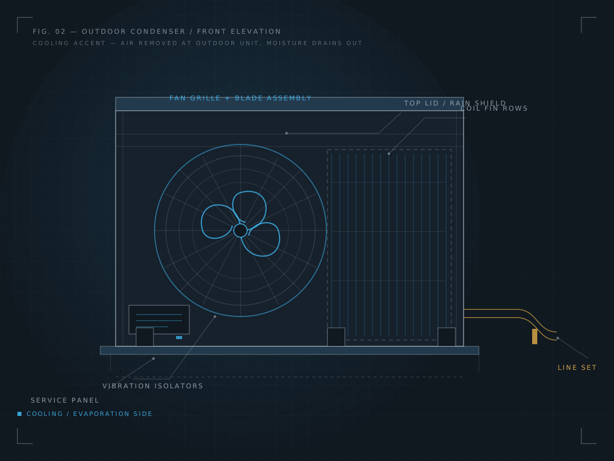
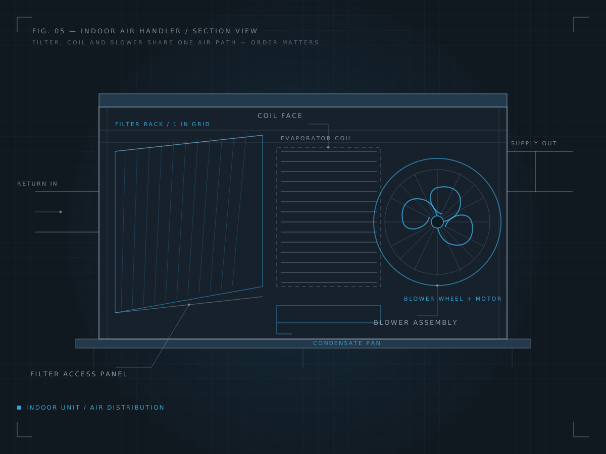
A central air conditioner is two separate boxes joined by a line set. The outdoor condenser is where heat is rejected to the outside air. The indoor air handler is where air is pulled in, filtered, cooled, and pushed back into the rooms. Air travels between them through the duct system, not through the refrigerant line.
Because the two halves are separated by ductwork and a thermostat, the room you are standing in is a poor place to judge the system. What the vents deliver depends on the air handler, the duct run, and how much air the return system is pulling back.
- Central AC
- A split system, not a window unit — the capacity sits in the outdoor cabinet and the air is conditioned at the indoor cabinet.
- Outdoor condenser
- Fan and coil that release heat outdoors. A condenser that cannot move air, or has restricted airflow around it, will not shed heat properly.
- Indoor air handler
- Filter, evaporator coil and blower in one cabinet. Air crosses the coil, picks up heat, and returns to the rooms through the ducts.
- Refrigerant symptoms
- Weak cooling, a line that stays warm well into the run, or ice forming on the line set often points at the charge or the circuit, not the thermostat.
- Airflow restrictions
- A clogged filter, closed registers or crushed flex duct all reduce the air crossing the coil — which lowers the temperature leaving the vents.
- Thermostat operation
- The thermostat calls for cooling and the system responds. If the call is not reaching the equipment, the problem is in the control path, not the cooling loop.
03 HEATING
Furnaces, heat pumps and the start-up sequence
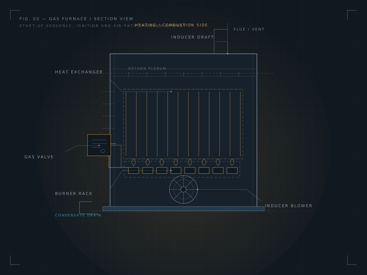
Heating equipment has a defined order of operations. The thermostat calls for heat, the control checks its switches, the draft is proven, the gas valve opens, the burners light, and the system only runs once the sensing elements confirm what the flame is doing. A failure at any step produces a house that is warm at the thermostat and cold at the registers.
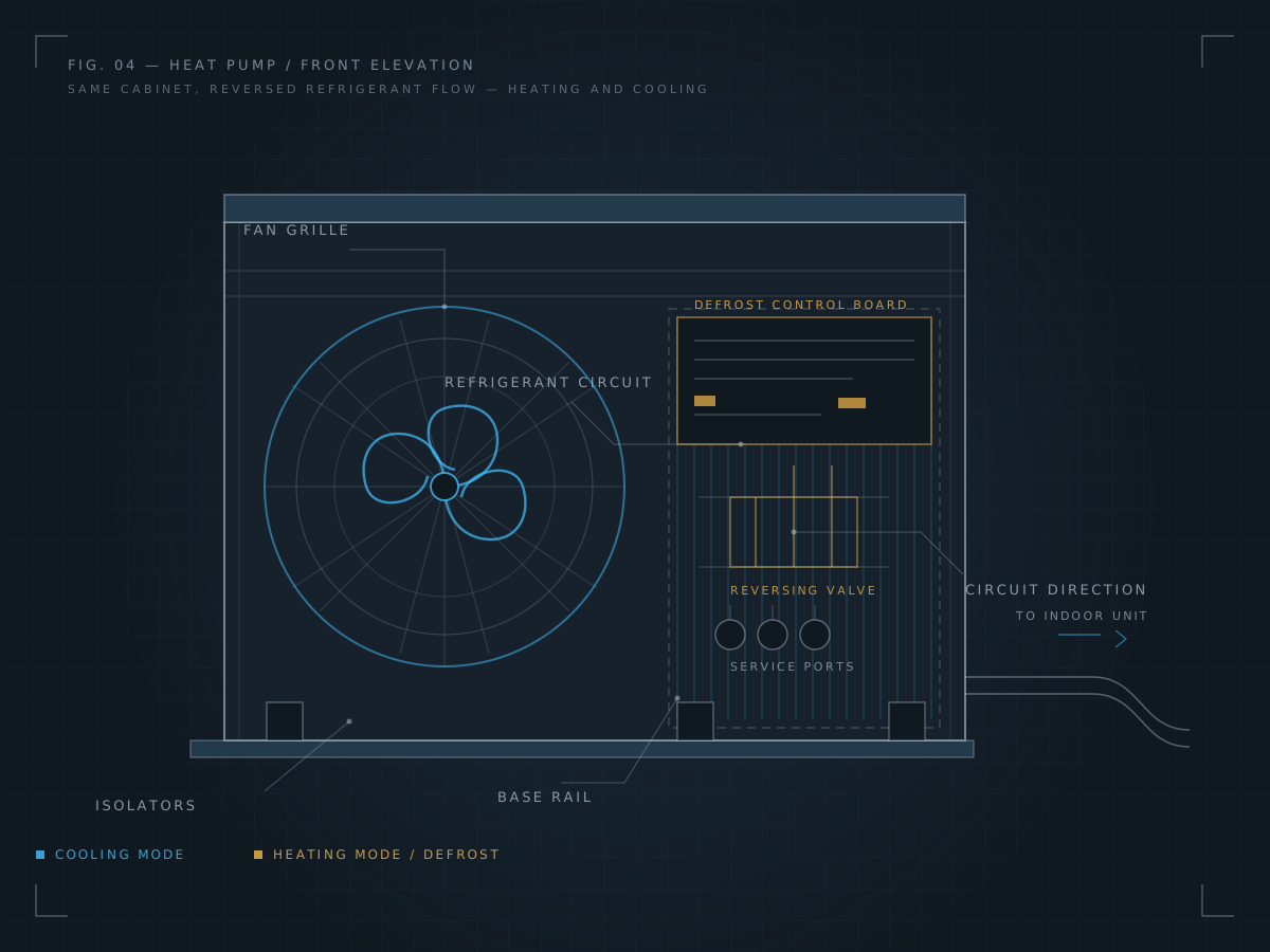
A heat pump reverses the same refrigerant circuit instead of burning fuel, so its weak-heating complaints tend to appear along with a cooling complaint, or right after a change in weather when defrost cycles start appearing in the run pattern.
- Furnaces
- Gas or electric. Gas furnaces light burners; electric furnaces use elements and are limited by how much power the circuit can carry.
- Heat pumps
- Move heat rather than create it. In heating mode the outdoor coil is the evaporator and the indoor coil is the condenser.
- Ignition & start-up
- Click-without-run, a delay then a bang, or a brief blast of heat then nothing usually traces to a control, a limit switch or a failing igniter.
- Uneven heating
- Rooms downstream of a starved branch run will lag behind the rest of the house even with the furnace working correctly.
- Airflow issues
- Too little air across a furnace can trip high-limit controls and cut the cycle short, which reads to a homeowner as short cycling.
- Thermostat problems
- Heat called for and never delivered usually means the call is not arriving, or the equipment is being shut down by one of its own limits.
04 SERVICES
HVAC Service
General reference for common system complaints. Each row describes what is inspected and the service that may follow — it is not a diagnosis and it does not predict a part, a price or a result.
| System | Common Issue | Inspection Focus | Possible Service |
|---|---|---|---|
| Air Conditioner | Weak cooling, warm supply air | Coil condition, airflow, line set temps | Coil cleaning, airflow correction, refrigerant service |
| Furnace | No heat, short cycling, noise at start | Ignition sequence, limit switches, flue | Igniter or control service, limit switch replacement, burner cleaning |
| Heat Pump | Heating or cooling reduced | Mode change, defrost behaviour, line set | Reversing valve or control service, defrost sensor, refrigerant service |
| Thermostat | System ignores settings, wrong room reading | Type, placement, schedule, control wiring | Relocation, re-programming, replacement or control wiring repair |
| Air Handler | Low airflow, blower noise, no cooling | Filter, coil, blower wheel, motor, drain | Coil cleaning, drain clearing, blower or capacitor service |
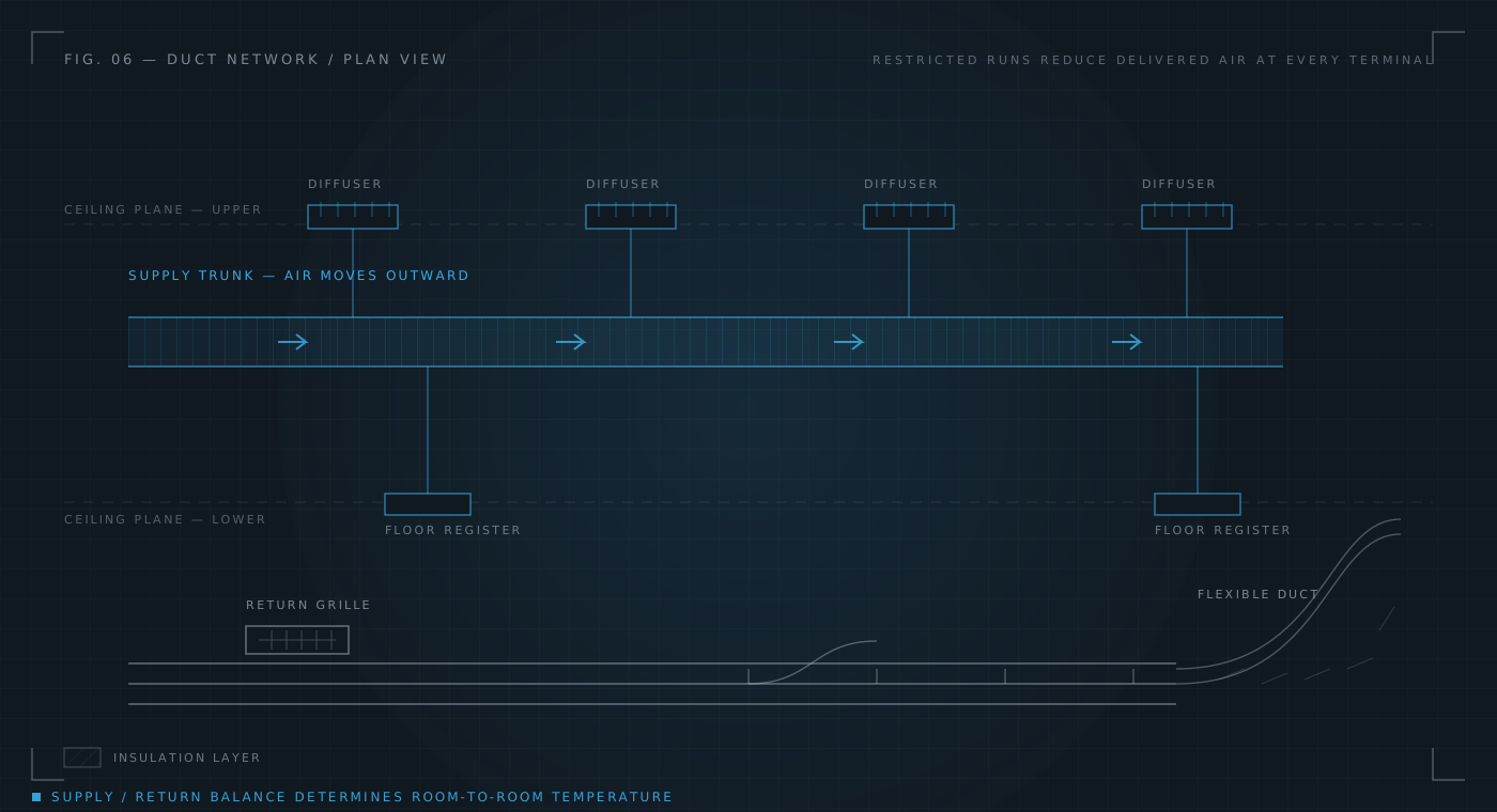
| Ductwork | Uneven rooms, whistling, weak registers | Static pressure, run sizing, return balance | Damper adjustment, branch repair, sealing and insulation |
Cooling side of the system Heating side of the system Control and air distribution
04.1 REPAIRS
When a part, and not an adjustment, is the next step
Repairs follow inspection, not the other way around. A control that has been confirmed not responding, a coil that is damaged, or a blower motor that will not turn are repair items. Restricted airflow, a bad filter setting, or a schedule that was never programmed are not — they are settings and maintenance items that do not require a new component.
-
Confirmed component failures
When a part has been tested and shown not to work, it is replaced rather than adjusted or reset.
-
Before anything is ordered
The fault is narrowed to a specific part first, so the right part is ordered once instead of guessed at twice.
-
What a repair does not cover
Undersized ductwork, a thermostat in the wrong room, or a system that was never sized for the house are not part failures.
-
Repeat failures on the same system
Two different components in one cabinet usually means the underlying cause is upstream of both, and is worth finding.
05 CONTACT
Start with a description of
what the system is doing
The most useful first conversation is a plain description: which rooms are affected, what the air feels like at the vents, when it happens, and what the equipment does when it starts. That is usually enough to know which part of the system needs to be looked at first.
Telephone
728-231-5442Call and describe the symptom: which rooms are affected, when it happens, and what the equipment does when it starts.